Code
print("Hello, B.Tech Students!")Hello, B.Tech Students!Aim
This session introduces the fundamental libraries that make Python a powerhouse for engineering.
NumPy, Matplotlib, and SymPyObjective: To get comfortable creating arrays, plotting data, and performing symbolic calculations.
Python coding with colab
You can complete your experiments using colab- A cloud jupyter notebook. Please use the following link to run Python code in colab. https://colab.google/ (Right click and open in a new tab)
The classic first program for any language.
print("Hello, B.Tech Students!")Hello, B.Tech Students!Introduction to different data types like integers, floats, and strings.
x = 10  # Integer
y = 3.5  # Float
name = "Python"  # String
is_student = True  # Boolean

print(x, y, name, is_student)
10 3.5 Python TrueUsing if, elif, and else statements.
x = 10  # Integer
if x>5:
    print("x is greater than 5")
elif x==5:
    print("x is 5")
else:
    print("x is less than 5")
x is greater than 5Using for and while loops.
# For loop
for i in range(5):
    print("Iteration:", i)
Iteration: 0
Iteration: 1
Iteration: 2
Iteration: 3
Iteration: 4# While loop
n = 0
while n < 3:
print("While loop iteration:", n)
n += 1While loop iteration: 0
While loop iteration: 1
While loop iteration: 2Defining and calling functions.
def add_numbers(a, b):
    return a + b

result = add_numbers(5, 3)
print("Sum:", result)
Sum: 8NumPyNumPy is useful for numerical operations.
#Solve 2x+3y=54x+4y=6
import numpy as np

A = np.array([[2, 3], [4, 4]])
b = np.array([5, 6])

x = np.linalg.solve(A, b)
print("Solution:", x)
Solution: [-0.5 2. ]Matplotlib is used for simple visualizations. Install using: pip install matplotlib
#Plotting a sine wave
import matplotlib.pyplot as plt
import numpy as np

x = np.linspace(0, 10, 100)
y = np.sin(x)

plt.plot(x, y)
plt.xlabel("x")
plt.ylabel("sin(x)")
plt.title("Sine Wave")
plt.show()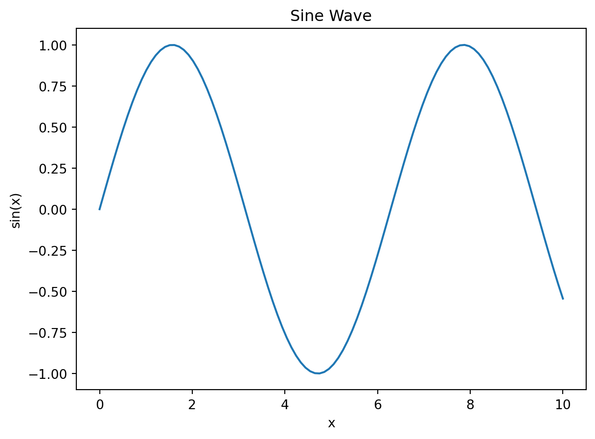
import numpy as np
import matplotlib.pyplot as plt

# Parameters
Vs = 5.0  # Source voltage (Volts)
R = 1000  # Resistance (Ohms)
C = 1e-6  # Capacitance (Farads)
tau = R * C # Time constant

# Create a time vector from 0 to 5*tau
t = np.linspace(0, 5 * tau, 100)

# Calculate voltage using the formula
Vc = Vs * (1 - np.exp(-t / tau))

# Plotting the result
plt.figure(figsize=(8, 5))
plt.plot(t, Vc, label=f'RC = {tau}s')
plt.title('Capacitor Charging Voltage')
plt.xlabel('Time (s)')
plt.ylabel('Voltage (V)')
plt.grid(True)
plt.legend()
plt.show()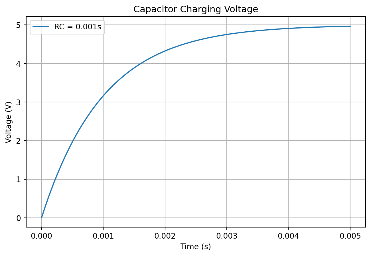
SciPy provides numerical solvers for differential equations and optimizations.
Scipy
The Scipy library can be installed using the pip install scipy command in terminal or using !pip install scipy in colab.
#Solving a Simple PDE ∂u/∂x + ∂u/∂t=0
from sympy import symbols, Function, Eq, Derivative, pdsolve

# Define variables
x, t = symbols('x t')
u = Function('u')(x, t)

# Define a simple PDE: ∂u/∂x + ∂u/∂t = 0
pde = Eq(Derivative(u, x) + Derivative(u, t), 0)

# Solve the PDE using pdsolve
solution = pdsolve(pde)
# Print the solution
print(solution)
Eq(u(x, t), F(-t + x))# Example: Solving an ODE as an approximation for a PDE
from scipy.integrate import solve_ivp
import numpy as np
from scipy.integrate import solve_ivp
import numpy as np
import matplotlib.pyplot as plt
def pde_rhs(t, u):
return -0.5 * u # Example equation
sol = solve_ivp(pde_rhs, [0, 10], [1], t_eval=np.linspace(0, 10, 100))
plt.plot(sol.t, sol.y[0])
plt.xlabel('Time')
plt.ylabel('Solution')
plt.show()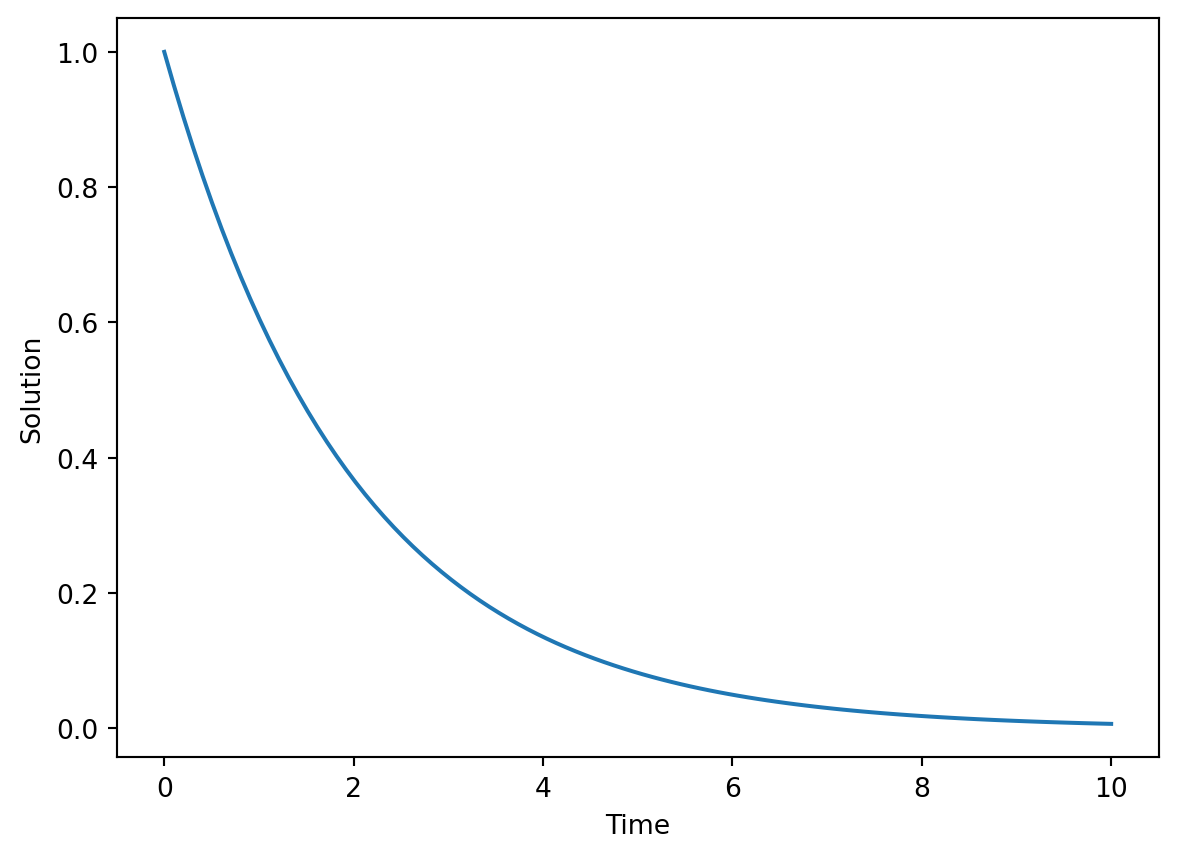
SymPySymPy is a symbolic mathematics library that can be used to derive analytical solutions to PDEs.
from scipy.optimize import minimize

def objective(x):
    return x**2 + 2*x + 1

result = minimize(objective, 0)  # Start search at x=0
print("Optimal x:", result.x)
Optimal x: [-1.00000001]Concept: In electronics, continuous analog signals (like AC voltage) are sampled at discrete time intervals to be processed by a digital system (like a microcontroller or computer). A NumPy array is the perfect way to store these sampled values.
Python Skills: * np.linspace(): To create an array of evenly spaced time points. * np.sin(): An element-wise function that applies the sine function to every value in an array.
Task: Generate and plot a 50 Hz sine wave voltage signal with a peak voltage of 5V, sampled for 3 cycles.
import numpy as np
import matplotlib.pyplot as plt

# --- Parameters ---
frequency = 50  # Hz
peak_voltage = 5.0  # Volts
cycles = 3
sampling_rate = 1000 # Samples per second

# --- Time Array Generation ---
# Duration of 3 cycles is 3 * (1/frequency)
duration = cycles / frequency
# Create 1000 points per second * duration
num_samples = int(sampling_rate * duration)
t = np.linspace(0, duration, num_samples)

# --- Signal Generation ---
# The formula for a sine wave is V(t) = V_peak * sin(2 * pi * f * t)
voltage = peak_voltage * np.sin(2 * np.pi * frequency * t)

# --- Visualization ---
plt.figure(figsize=(10, 4))
plt.plot(t, voltage)
plt.title('Digital Representation of a 50 Hz Sine Wave')
plt.xlabel('Time (s)')
plt.ylabel('Voltage (V)')
plt.grid(True)
plt.show()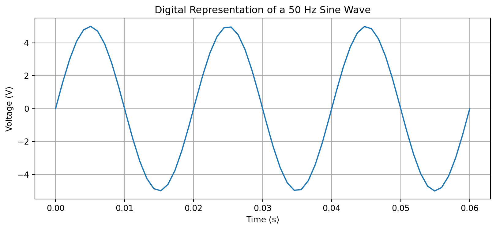
Concept: Real-world sensor data is never perfect. It’s often corrupted by random noise. We can simulate this by adding a random component to our ideal signal.
Python Skills:
Array Addition: Simply using + to add two arrays of the same shape.
np.random.normal(): To generate Gaussian noise, which is a common model for electronic noise.
Task: Take the 5V sine wave from the previous example and add Gaussian noise with a standard deviation of 0.5V to simulate a noisy sensor reading.
# We can reuse the 't' and 'voltage' arrays from the previous example
noise_amplitude = 0.5 # Standard deviation of the noise in Volts

# Generate noise with the same shape as our voltage array
noise = np.random.normal(0, noise_amplitude, voltage.shape)

# Create the noisy signal by adding the noise to the ideal signal
noisy_voltage = voltage + noise

# --- Visualization ---
plt.figure(figsize=(10, 4))
plt.plot(t, voltage, label='Ideal Signal', linestyle='--')
plt.plot(t, noisy_voltage, label='Noisy Sensor Reading', alpha=0.75)
plt.title('Ideal vs. Noisy Signal')
plt.xlabel('Time (s)')
plt.ylabel('Voltage (V)')
plt.legend()
plt.grid(True)
plt.show()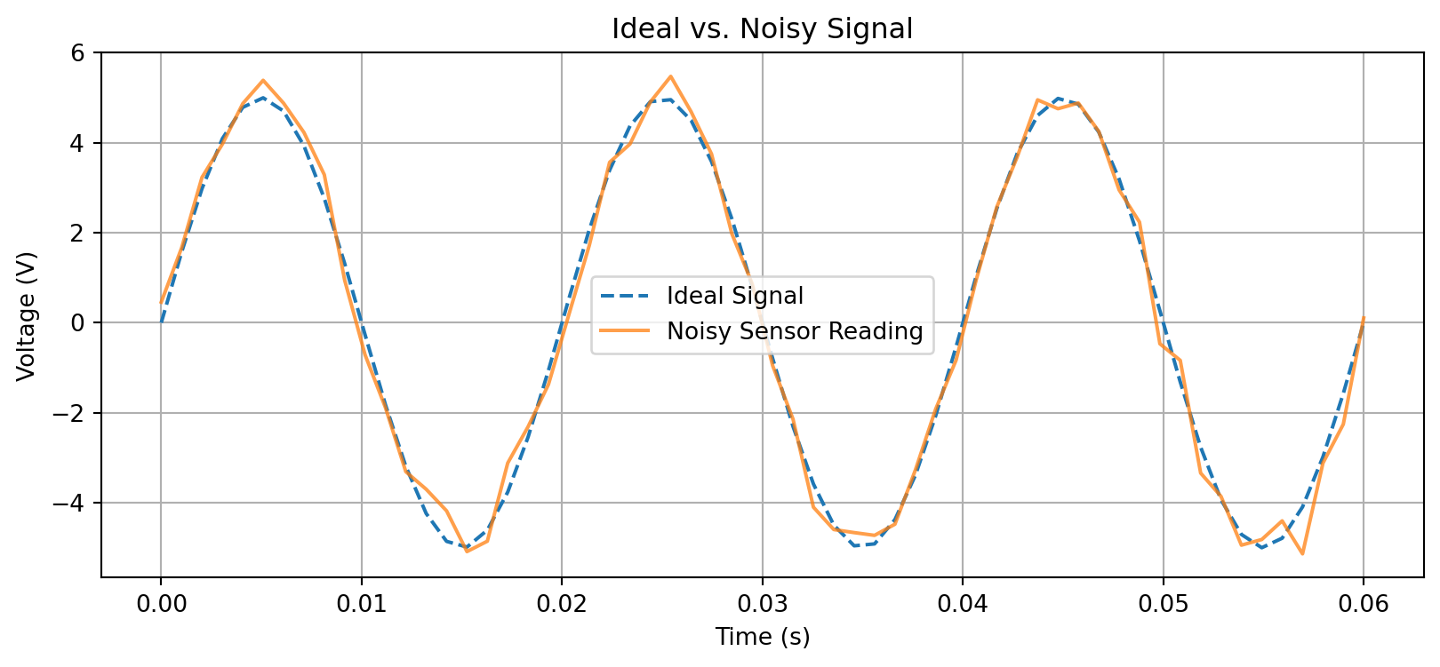
Concept: Forward kinematics in robotics is the process of calculating the position of the robot’s end-effector (e.g., its gripper) based on its joint angles. For a simple 2D arm, this involves basic trigonometry.
Python Skills:
np.cos, np.sin, np.deg2rad).Task: Calculate and plot the position of a 2-link planar robot arm with link lengths L1=1.0m and L2=0.7m for given joint angles theta1=30° and theta2=45°.
# --- Parameters ---
L1 = 1.0  # Length of link 1
L2 = 0.7  # Length of link 2
theta1_deg = 30
theta2_deg = 45

# Convert angles to radians for numpy's trig functions
theta1 = np.deg2rad(theta1_deg)
theta2 = np.deg2rad(theta2_deg)

# --- Kinematics Calculations ---
# Position of the first joint (end of L1)
x1 = L1 * np.cos(theta1)
y1 = L1 * np.sin(theta1)

# Position of the end-effector (end of L2) relative to the first joint
# The angle of the second link is theta1 + theta2
x2 = x1 + L2 * np.cos(theta1 + theta2)
y2 = y1 + L2 * np.sin(theta1 + theta2)

# --- Visualization ---
plt.figure(figsize=(6, 6))
# Plot the arm links
plt.plot([0, x1], [0, y1], 'r-o', linewidth=3, markersize=10, label='Link 1')
plt.plot([x1, x2], [y1, y2], 'b-o', linewidth=3, markersize=10, label='Link 2')

# Plot the base and end-effector positions for clarity
plt.plot(0, 0, 'ko', markersize=15, label='Base')
plt.plot(x2, y2, 'gX', markersize=15, label='End-Effector')

plt.title('2-Link Robot Arm Kinematics')
plt.xlabel('X Position (m)')
plt.ylabel('Y Position (m)')
plt.grid(True)
plt.axis('equal') # Important for correct aspect ratio
plt.legend()
plt.show()

print(f"End-effector is at position: ({x2:.2f}, {y2:.2f})")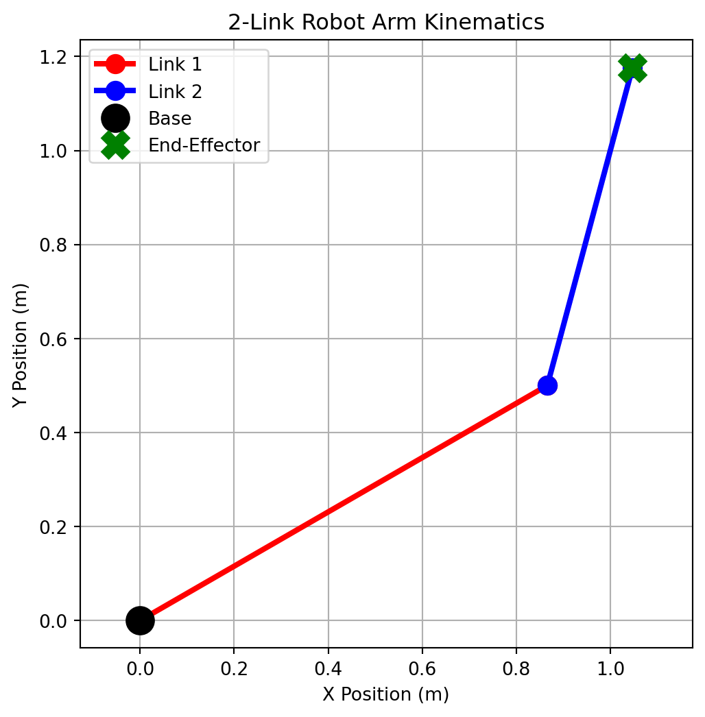
End-effector is at position: (1.05, 1.18)Concept: A robot often has sensors (like a camera or a Lidar) mounted at an angle. To understand the sensor data in the robot’s own coordinate frame, we need to rotate the data points. This is a fundamental operation in robotics and computer vision, done using a rotation matrix.
Python Skills:
Creating a 2D NumPy array (a matrix).
Matrix multiplication using the @operator.
Transposing an array (.T) for correct multiplication dimensions.
Task: A sensor detects an object at coordinates (2, 0) in its own frame. The sensor is rotated 45 degrees counter-clockwise relative to the robot’s base. Find the object’s coordinates in the robot’s frame.
# Angle of the sensor relative to the robot
angle_deg = 45
angle_rad = np.deg2rad(angle_deg)

# Point detected in the sensor's frame [x, y]
p_sensor = np.array([[2], [0]]) # As a column vector

# 2D Rotation Matrix
# R = [[cos(theta), -sin(theta)],
#      [sin(theta),  cos(theta)]]
R = np.array([[np.cos(angle_rad), -np.sin(angle_rad)],
              [np.sin(angle_rad),  np.cos(angle_rad)]])

# The transformation: p_robot = R @ p_sensor
p_robot = R @ p_sensor

# --- Visualization ---
plt.figure(figsize=(6, 6))
# Plot sensor's axes
plt.quiver(0, 0, np.cos(angle_rad), np.sin(angle_rad), color='r', scale=3, label="Sensor x'-axis")
plt.quiver(0, 0, -np.sin(angle_rad), np.cos(angle_rad), color='g', scale=3, label="Sensor y'-axis")

# Plot the point in the robot's frame
plt.plot(p_robot[0], p_robot[1], 'bo', markersize=10, label='Point in Robot Frame')
# For context, let's show where the point was in the sensor's frame (if it weren't rotated)
# This is just for visualization
plt.plot(p_sensor[0], p_sensor[1], 'ko', markersize=10, alpha=0.5, label='Original point (relative to axes)')


plt.axhline(0, color='black', linewidth=0.5)
plt.axvline(0, color='black', linewidth=0.5)
plt.grid(True)
plt.axis('equal')
plt.xlim(-1, 3)
plt.ylim(-1, 3)
plt.title("Coordinate Frame Rotation")
plt.xlabel("Robot X-axis")
plt.ylabel("Robot Y-axis")
plt.legend()
plt.show()

print("Rotation Matrix:\n", np.round(R, 2))
print(f"\nPoint in Sensor Frame: {p_sensor.flatten()}")
print(f"Point in Robot Frame:  {np.round(p_robot.flatten(), 2)}")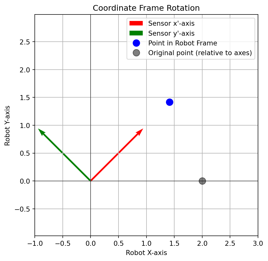
Rotation Matrix:
 [[ 0.71 -0.71]
 [ 0.71  0.71]]

Point in Sensor Frame: [2 0]
Point in Robot Frame: [1.41 1.41]Concept: To clean up the noisy signal from Example 3, we can apply a digital filter. The simplest is a moving average filter, which replaces each data point with the average of itself and its neighbors. This smooths out sharp fluctuations (noise).
Python Skills:
np.mean(): To calculate the average of a set of numbers.Task: Apply a 5-point moving average filter to the noisy_voltage signal created in Example 3 and plot the result to see the smoothing effect.
# Let's regenerate the noisy signal for a self-contained example
# (In a real notebook, you would reuse the variable from before)
frequency = 50
peak_voltage = 5.0
duration = 3 / frequency
t = np.linspace(0, duration, int(1000 * duration))
voltage = peak_voltage * np.sin(2 * np.pi * frequency * t)
noise = np.random.normal(0, 0.5, voltage.shape)
noisy_voltage = voltage + noise

# --- Filtering ---
window_size = 5
# Create an empty array to store the filtered signal
filtered_voltage = np.zeros_like(noisy_voltage)

# Loop through the signal. We can't compute a full window at the very edges,
# so we'll just copy the original values for the first and last few points.
for i in range(len(noisy_voltage)):
    # Find the start and end of the slice
    start = max(0, i - window_size // 2)
    end = min(len(noisy_voltage), i + window_size // 2 + 1)

    # Get the window of data and calculate its mean
    window = noisy_voltage[start:end]
    filtered_voltage[i] = np.mean(window)

# --- Visualization ---
plt.figure(figsize=(10, 4))
plt.plot(t, noisy_voltage, label='Noisy Signal', alpha=0.5)
plt.plot(t, filtered_voltage, label='Filtered Signal', color='r', linewidth=2)
plt.title('Effect of Moving Average Filter')
plt.xlabel('Time (s)')
plt.ylabel('Voltage (V)')
plt.legend()
plt.grid(True)
plt.show()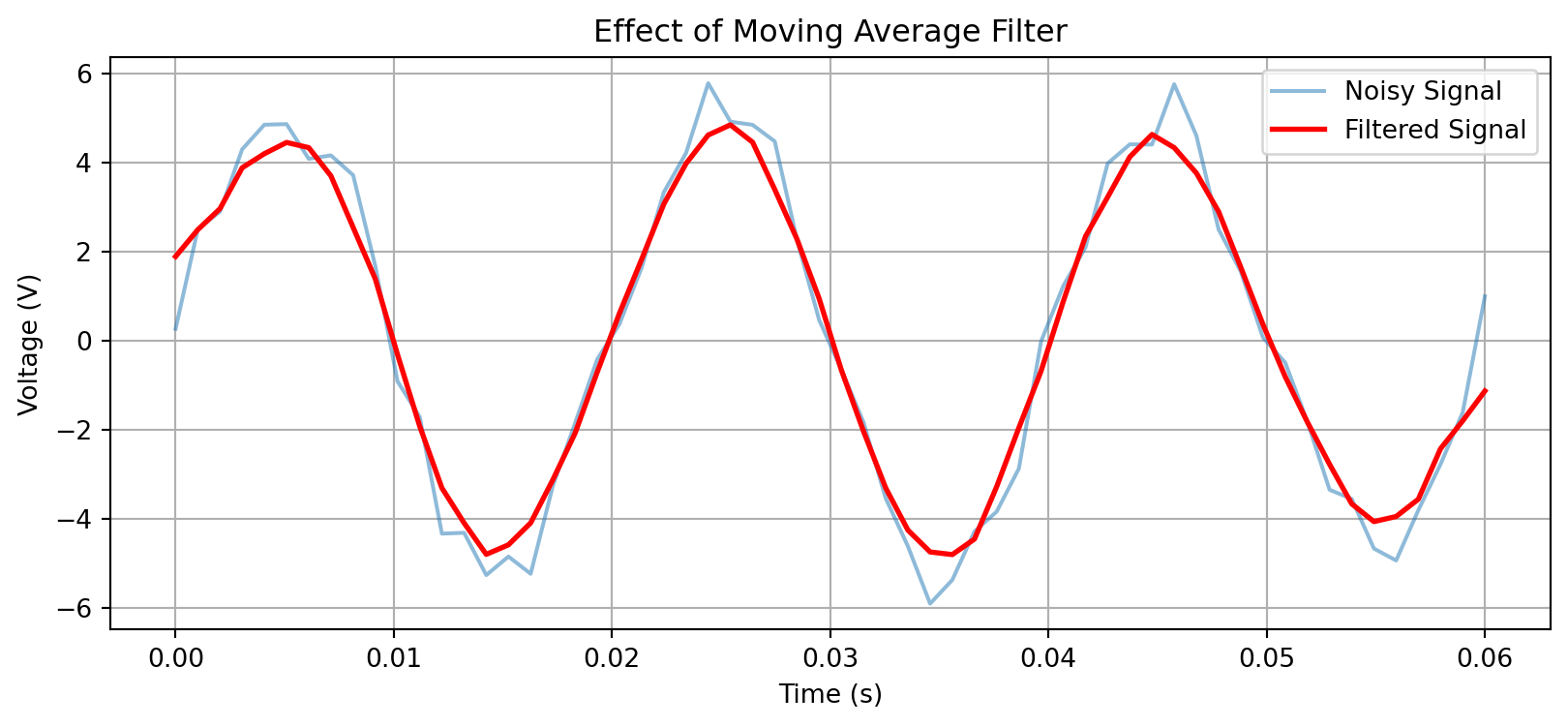
Now that you have mastered NumPy, Matplotlib, and SymPy, we will use these exact tools to visualize and solve the first major topic of your theory syllabus: Formation of Partial Differential Equations.
In your theory class, you will learn that a surface like a plane: \[z=ax+by+k\] (where \(a\),\(b\) are arbitrary constants, and \(k\) is system parameter) can be differentiated to eliminate these constants.
Step 1: Find the partial derivatives:
\[\begin{align*} p&=a\\ q&=b \end{align*}\]
Step 2: Substitute \(a\)and \(b\) back into \(z=ax+by+k\), we get
\(px+qy-z+c=0\).
A single PDE represents an infinite family of surfaces. Every possible value of the arbitrary variable gives a different plane, but they will obey the same PDE!
The code below creates an interactive 3D plot of the plane \(x=ax+by+k\). Use the sliders to change \(a\) and \(b\). and watch the plane tilt. The text box on the left shows the partial derivatives and verifies that the PDE \(px+qy-z+k=0\) always equals zero.
import numpy as np
import matplotlib.pyplot as plt
from matplotlib.widgets import Slider

# ==========================================
# Step 1: SETUP THE 3D FIGURE & GRID
# ==========================================
fig = plt.figure(figsize=(10, 8))
ax = fig.add_subplot(111, projection='3d')
plt.subplots_adjust(bottom=0.25)

# Create the spatial coordinates (x, y)
x = np.linspace(-10, 10, 20)
y = np.linspace(-10, 10, 20)
X, Y = np.meshgrid(x, y)

# Initial arbitrary constants
a_init = 1.0
b_init = 1.0
k_const = 5.0

def calculate_surface(a, b, k):
    return k - a * X - b * Y

# ==========================================
# Step 2. INITIAL PLOT & TEXT ANNOTATION
# ==========================================
Z = calculate_surface(a_init, b_init, k_const)
surf = ax.plot_surface(X, Y, Z, cmap='plasma', alpha=0.8)

def format_axes():
    ax.set_xlabel('Spatial X')
    ax.set_ylabel('Spatial Y')
    ax.set_zlabel('Voltage (Z)')
    ax.set_title('Family of Planes: ax + by + z = k')
    ax.set_zlim(-30, 30)

format_axes()

# Text box
props = dict(boxstyle='round', facecolor='white', alpha=0.9, edgecolor='gray')
text_box = fig.text(0.05, 0.90, '', transform=fig.transFigure, fontsize=11,
                    verticalalignment='top', family='monospace', bbox=props)

def update_text(a, b):
    p = -a  # dz/dx
    q = -b  # dz/dy
    text_str = (f"Current Constants:\n"
                f"a = {a:5.2f}  |  b = {b:5.2f}\n\n"
                f"Partial Derivatives:\n"
                f"p (dz/dx) = {p:5.2f}\n"
                f"q (dz/dy) = {q:5.2f}\n\n"
                f"Checking the formulated PDE:\n"
                f"px + qy - z + k = 0.00")
    text_box.set_text(text_str)

update_text(a_init, b_init)

# ==========================================
# Step 3. INTERACTIVE SLIDERS
# ==========================================
axcolor = 'lightgray'
ax_a = plt.axes([0.2, 0.15, 0.65, 0.03], facecolor=axcolor)
ax_b = plt.axes([0.2, 0.10, 0.65, 0.03], facecolor=axcolor)

slider_a = Slider(ax_a, 'Constant a', -3.0, 3.0, valinit=a_init)
slider_b = Slider(ax_b, 'Constant b', -3.0, 3.0, valinit=b_init)

def update(val):
    a = slider_a.val
    b = slider_b.val
    ax.clear()
    Z_new = calculate_surface(a, b, k_const)
    ax.plot_surface(X, Y, Z_new, cmap='plasma', alpha=0.8)
    format_axes()
    update_text(a, b)
    fig.canvas.draw_idle()

slider_a.on_changed(update)
slider_b.on_changed(update)

plt.show()The variables \(a\) and \(b\) are not just abstract numbers—they have physical meaning in your field. Consider a 2D PCB copper plane (like a ground plane). The voltage \(V(x,y)\) drops linearly due to the resistance of the copper. Using Ohm’s law in 2D: \[ V(x,y)=V_0-E_x\cdot x-E_y \cdot y\]
where \(E_x\) and \(E_y\) are the electric field components (voltage gradients) in the x and y directions. Comparing this with our plane equation, we can see that:
The PDE \(px+qy-z+k=0\) now describes the fundamental relationship between voltage gradients and the voltage distribution in any resistive medium. This is the same math that governs current flow in your PCBs!
Here is the interactive demo that shows how changing \(a\) and \(b\) (the electric field components) affects the voltage distribution across the plane.
# ==========================================
# COMPANION CODE: ECE INTERPRETATION OF PDE
# 2D Voltage Drop in a PCB Plane (Ohm's Law)
# ==========================================
import numpy as np
import matplotlib.pyplot as plt
from matplotlib.widgets import Slider

fig = plt.figure(figsize=(10, 8))
ax = fig.add_subplot(111, projection='3d')
plt.subplots_adjust(bottom=0.25)

# PCB dimensions (in cm)
x = np.linspace(0, 10, 30)
y = np.linspace(0, 10, 30)
X, Y = np.meshgrid(x, y)

# Physical parameters (mapped from arbitrary constants)
# a = Voltage gradient in X (V/cm)  →  E_x = -dV/dx
# b = Voltage gradient in Y (V/cm)  →  E_y = -dV/dy
a_init = 0.5  # V/cm
b_init = 0.3  # V/cm
V_ref = 5.0   # Reference voltage at origin (Volts)

def calculate_pcb_voltage(a, b, V0):
    # V(x,y) = V0 - a*x - b*y  (Linear voltage drop)
    return V0 - a * X - b * Y

Z = calculate_pcb_voltage(a_init, b_init, V_ref)
surf = ax.plot_surface(X, Y, Z, cmap='viridis', alpha=0.8)

ax.set_xlabel('X position on PCB (cm)')
ax.set_ylabel('Y position on PCB (cm)')
ax.set_zlabel('Voltage (V)')
ax.set_title('2D Voltage Distribution on a PCB Ground Plane')
ax.set_zlim(0, 6)

# Info box showing ECE interpretation
props = dict(boxstyle='round', facecolor='lightblue', alpha=0.9)
text_box = fig.text(0.05, 0.85, '', transform=fig.transFigure, fontsize=10,
                    verticalalignment='top', family='monospace', bbox=props)

def update_text(a, b):
    # Electric field components (negative gradient)
    Ex = a   # E_x = -dV/dx = a
    Ey = b   # E_y = -dV/dy = b
    text_str = (f"⚡ ECE Interpretation ⚡\n"
                f"Voltage gradient in X (a): {a:.2f} V/cm\n"
                f"Voltage gradient in Y (b): {b:.2f} V/cm\n\n"
                f"Electric Field Components:\n"
                f"E_x = -dV/dx = {a:.2f} V/cm\n"
                f"E_y = -dV/dy = {b:.2f} V/cm\n\n"
                f"📐 The PDE governing this:\n"
                f"∂V/∂x + ∂V/∂y = -({a+b:.2f}) V/cm\n"
                f"(This is a form of Laplace's equation)")
    text_box.set_text(text_str)

update_text(a_init, b_init)

# Sliders (now labeled with physical units)
ax_a = plt.axes([0.2, 0.15, 0.65, 0.03], facecolor='lightgray')
ax_b = plt.axes([0.2, 0.10, 0.65, 0.03], facecolor='lightgray')

slider_a = Slider(ax_a, 'Gradient a (V/cm)', 0.0, 1.5, valinit=a_init)
slider_b = Slider(ax_b, 'Gradient b (V/cm)', 0.0, 1.5, valinit=b_init)

def update(val):
    a = slider_a.val
    b = slider_b.val
    ax.clear()
    Z_new = calculate_pcb_voltage(a, b, V_ref)
    ax.plot_surface(X, Y, Z_new, cmap='viridis', alpha=0.8)
    ax.set_xlabel('X position on PCB (cm)')
    ax.set_ylabel('Y position on PCB (cm)')
    ax.set_zlabel('Voltage (V)')
    ax.set_title('2D Voltage Distribution on a PCB Ground Plane')
    ax.set_zlim(0, 6)
    update_text(a, b)
    fig.canvas.draw_idle()

slider_a.on_changed(update)
slider_b.on_changed(update)

plt.show()Before we jump into the challenges, look at how your practice tasks prepared you for this:
| Day-1 Skill | How it applies to Module-I PDEs |
|---|---|
T-1 (Sine wave with np.linspace) |
You will use np.linspace to create spatial grids (x, y) for 2D PDE problems. |
| T-3 (Robot arm kinematics) | Finding the “characteristic curves” in Lagrange’s method is exactly like following the robot’s joints—you trace a path to find the solution. |
| T-4 (Rotation matrix) | Changing variables in PDEs (like separation of variables) is a coordinate transformation, just like rotating a sensor frame! |
| T-5 (Moving average filter) | Numerical methods for PDEs (like Finite Difference) use sliding windows over the grid, similar to your filtering loop. |
sympy.pdsolve (Basic example) |
You already solved ∂u/∂x + ∂u/∂t = 0. Now you will solve real engineering PDEs. |